 (By permission of Brian Basset, 12/14/2022).
Reflections…
Introduction
Preparation for the Apollo 17 mission began several years before I had been selected as a functioning crew member. Prior to my first crew assignment, I “stole” as much simulator time as I could, ranging from early mockup displays put together by the Flight Controllers in Building 30, to times when crews were not using the Command and Service Module (CSM) and Lunar Module (LM) simulators in Houston, to times after a mission launch when the same simulators were not in use at the Cape. I also assumed as many hardware and operations activities as I could, including developing the advanced geological training program for assigned crews, watching over the Lunar Module Descent Stage stowage, flight planning for the lunar portions of Apollo 8 and 10, assisting in the development of malfunction procedures for both the CSM and LM, helping with trouble-shooting in Mission Control during Apollos 8-12 and 14-16. For Apollo 13, I was already using the simulators at the Cape when the explosion occurred, so I began to verify the new recovery procedures before they were sent to the crew. I also flew as many aerobatic and cross-country hours as possible in the T-38↑ (jet) and comparable time in the local area in the H-13 (helicopter).
In January of 1970, my boss, Alan Shepherd, notified me that I was getting a crew assignment, so simulator time became a priority over all else. Beginning in April of that year, I began 15 months training with Dick Gordon and Vance Brand as the back-up crew for Apollo 15. The usual crew rotation schedule would have placed the three of us as the prime crew for Apollo 18, but when that mission was canceled, NASA Headquarters management told Deke Slayton, the big boss, that he should put me on Apollo 17. Commander Gene Cernan, Command Module Pilot Ron Evans, and Lunar Module Pilot Joe Engle, as the Backup Crew for Apollo 14, were in the expected, but not always firm, line to crew Apollo 17. Deke’s choices were to assign Dick Gordon’s Apollo 15 Backup Crew to 17, or to substitute me for Joe Engle as the Lunar Module Pilot on Apollo 17. Deke chose the latter option. Headquarters and many others felt that no scientist had yet flown to the Moon, and as a geologist, I was not only the only choice but was fully prepared. Thus, I was given the opportunity to go on this final mission to the Moon, as well as another 15 months of crew training.
Launch
With training behind us, the Apollo 17 crew was finally strapped into our couches in Command Module (CM) America, going through final preparation for launch. As the launch countdown reached 30 seconds just shy of 10:00 PM on December 6, 1972, the launch sequence was stopped. After about five minutes, we were informed by Skip Chavin that the Terminal Countdown Sequencer computer thought that a liquid oxygen tank in the Saturn V’s S-II second stage had not been pressurized even though it had been by an alert human launch controller. The failure in the Terminal Countdown Sequencer’s understanding was soon bypassed and tested. At precisely 12:33:00 a.m. EST December 7, 1972, after a 2 hour, 40 minute launch delay, seven and one half million pounds of pulsing, crackling thrust from the Saturn’s five huge, F-1 first stage engines, burning kerosene and liquid oxygen, first started to shake us and the rocket and then lifted us toward space, turning night into day. Except for the small window directly in front of the Commander, the Command Module (CM) windows were covered by a heat shield shroud connected to the escape tower and rocket so that we were protected from the escape tower rocket exhaust should we need to abort the launch. Thus, we missed the display witnessed by over a million viewers of the launch of Apollo 17, the last of the Apollo missions to the Moon.
The heavy, low frequency vibration on the S-I first stage ended at about 2 min and 45 sec with S-I shutdown and S-II stage ignition. That sequence took us from about plus 4.5 g’s, to a minus 1.5 g’s, to a smooth, plus 1.5 g’s in just over a second. That got our attention! You know why you are strapped firmly onto your couch. After about 9 minutes, the third stage S-IVB took over and about 10 minutes after launch we were in orbit and weightless. My experience with weightlessness was very pleasant, but then I had planned to limit my head and body motions, so as a result all I felt for a few days was an occasional light headache and slight stomach awareness. My two companions were not so fortunate.
 Fig. 1. Lift off of Apollo 17 from Kennedy Space Center Pad 39A at 12:33 a.m. EST on Dec. 7, 1972. The CM is protected by a white shroud heat shield completely closing off all but one of the windows and the entry/escape hatch. (NASA/UPI photo).
As we approached the West Coast on Orbit 2 of the Earth about one and a half hours after launch (Mission Control was checking telemetry on all our systems in order give us a “GO” for the Moon), I referred to the lights of California, saying “Man’s field of stars on the Earth is competing with the heavens, Bob”. It was an unforgettable sight, as many other views would also prove to be in the ensuing days. A few minutes later I asked Bob Overmeyer, our Launch Capcom, if we were south of Arizona where my mother and my sister’s family were together and listening to the communications. He replied that we were over Mexico about 100 miles south of the border. Although there was ~70% cloud cover in Florida at our launch, the night below us was perfectly clear, except for north of the border. Only the glow of small city lights under the clouds gave an indication of where my New Mexico home was located.

Fig. 2. This image of city lights was created in 2013 with data from the Suomi NPP – VIIRS satellite instrument. The view of California is an approximation of what I saw in 1971. (NASA Earth Observatory photo).
Translunar Injection (TLI) and Translunar Coast (TLC)
Translunar Injection (TLI) took place over the South Atlantic near the end of Orbit 2. The S-IVB third stage fired for 351 sec at 03:12:36.60 and we were off to the Moon. One of the first major tasks afterwards was for Command Module Pilot Ron Evans to separate the Command and Service Module (CSM) America from the S-IVB, turn us around, dock with the Lunar Module (LM), and extract the combination spacecraft in preparation for Translunar Coast (TLC). With Challenger in tow, the spacecraft were then put into a slow rotation perpendicular to the Sun’s rays to even out solar heating, i.e., the “barbecue” mode of flight.
About 5 hrs, 6 min into the mission, or roughly 26 min after the CSM-LM linkup and separation from the S-IVB, I was able to take a couple of remarkable photographs of the nearly full Earth (“Blue Marble”) from a distance of about 15,000 miles. This view of the full Earth is one of the most frequent downloads by the public from NASA archives. Throughout the TLC, I maintained a running commentary on the cloud and weather patterns along with a continued string of photographic images, the first such synoptic weather observations of the full Earth ever reported. After the mission, the National Oceanic and Atmospheric Association (NOAA) gave me a special meteorological Public Service Award for these observations.
As a Geologist, however, the relationships of the landmasses to each other also particularly affected me. Later, I wrote, “Like childhood’s home which we now only visit, changing in time but unchanged in the mind, we could see the full Earth revolve beneath us. The serpentine coasts of South America and Africa, like pieces from a child’s wood block puzzle, bound the blue-black South Atlantic. The eastward bulge of the Amazon and the westward dent of the Congo appear to fit together so neatly that one can easily imagine their joint birth when an ancient super continent slowly began to split apart to form a new ocean.”
 Fig. 3. This photo of the full Earth is unique in that the translunar trajectory had swung far enough south so that the continent of Antarctica was plainly visible. It was the only view from the Apollo missions in which the Earth’s South Pole was apparent. It is a frequently downloaded image from the NASA archives; however, most of those reproductions show the oceans much too blue. The image given here was color-corrected by my editor and is the color I recall. (NASA photo AS17-148-22726).
 Fig. 4. A short while later, the Earth had rotated and our trajectory had shifted further East so that the continent of Australia had come into view. (NASA photo AS17-148-22747).
 Fig. 5. During the Apollo 17 mission, our communications were carried on via the antenna at Honeysuckle Creek (HSK) whenever Australia was in view. When the antenna became part of the Deep Space Network in late 1974, it was given the designation DSS44. Later, when it was moved to Tidbinbilla in 1982, the name was changed to DSS46. This photo of the antenna and Operations Center at HSK was taken by Hamish Lindsay. (Hamish Lindsay collection via Colin Mackellar).
Since the launch had been delayed, a small midcourse correction was performed, using (and testing) the Service Propulsion System (SPS) engine so that we would arrive at the Moon on the original timeline. At 65 hrs into the mission the Command Module clock was accordingly updated by adding 2 hrs 40 min so that planned events on the lunar surface would match the stated times in the checklists. Apart from regular housekeeping duties during TLC, we also performed experiments prepared by outside investigators. One of them was designed to provide information on fluid behavior in zero gravity, known as the ‘heat flow and convection’ experiment. Another was for us to wear eye patches to detect and describe the light flashes produced by cosmic rays interacting with the eyes that had been reported by previous astronauts. These flashes were quite remarkable, but I could not help but wonder what the cosmic rays were doing to my brain!
On the second day of our flight, I entered the Lunar Module Challenger to make sure that nothing had come loose during the vibrations and shocks of the launch and to verify that we would have power and communications for landing on the Moon.
Nearness to Lunar Orbit Insertion (LOI) became quite apparent with the jettisoning of the Scientific Instrument Module (SIM) bay door at ~81 hrs, providing the metric mapping and panorama cameras unobstructed views from the Service Module. About this time, we also could see a thin crescent Moon out of our windows. Sunrise in the valley of Taurus-Littow was getting close as the slow rotation of the Moon continued.
 Fig. 6. The Apollo 17 backup flight metric mapping camera in the National Air and Space Museum (NASM). The film cassette is the white cylinder with handles at right. It held 460 m of 127 mm Panatomic-X 3400 aerial film sufficient for 3600 exposures of the lunar surface while the Command and Service Module (CSM) was in orbit. It was removed by Ron Evans on an EVA during the Transearth Coast (TEC) on our return journey. Successive frames overlapped by 78 percent and alternate frames by 57 percent. My editor photogrametrically processed hundreds of these photos, including those from the Apollos 15 and 16 missions, in the production of his book, Apollo Over the Moon in Perspective. (photo by the editor).
Lunar Orbit Insertion (LOI)
We entered lunar orbit 5 hrs later at 086:14 GET (Ground Elapsed Time) by the firing of the SPS engine for 393 sec. Soon after, I had my first view of the visible two-thirds of Earth rising above the lunar horizon.
The initial orbit was 170 x 52.6 n. mi. After 17 hrs of rest and checking systems in both the CSM and still attached LM, Cernan and I undocked and drifted away from our mother spacecraft. While we prepared the LM for Power Descent Initiation (PDI) and landing at our designated site in the Taurus-Littrow valley, Ron Evans made a small SPS burn which put the CSM into a 70 x 54 n. mi orbit where he would remain as gravitational forces gradually circularized his orbit to ~60 n. mi over the next 3 days.
On our last orbit prior to PDI, we had a great view along the valley we would explore during those 3 days. (an 11 minute flight over Taurus-Littrow based on this last orbit before landing, which I narrated for my editor’s book cited above, can be viewed here.)
 Fig. 7. View of the Command and Service Module (CSM) America crossing Bear Mt. and heading towards the South Massif just south of the valley of Taurus-Littrow on Apollo 17’s orbit prior to Challenger’s landing. Cernan took the photograph through his forward-looking window. The LM altitude is 25 km. (NASA Photo AS17-147-22465).
One of the issues that arose as Taurus-Littrow was being considered as a landing site was how to reduce the size of the landing errors so that possible dispersions would not include the steep slope of the North Massif wall of the narrow, 7 km wide valley. Houston’s Mission Planning and Analysis and Headquarter’s Bellcom engineers solved this problem by recommending the delay of the last update of our “state vector” (3 vectors representing our position in space and 3 vectors for our velocity) until just before PDI. This state vector determination was based on Ron’s sextant marks on small craters near our landing site taken on his previous orbit and processed in Mission Control. The positions of Ron’s craters were known relative to the Moon’s center of mass. This state vector update delay narrowed the error ellipse to a circle 1 km in diameter.
 Fig. 8. An anaglyph version with the CSM positioned just above the crest of the South Massif. (From Fig. 1, p. 115 of my editor’s 3D book Apollo on the Moon in Perspective (From NASA photos AS17-147-22466, -67)).
PDI and landing of the Challenger occurred without incident, other than the Commander’s brief excess rate of decent just prior to touchdown to which I quickly alerted him, as my job during the landing sequence was to operate the guidance computer (PNGS or “PINGS”) and call out landing point location data and then velocities provided through the computer’s display. After a few minutes wait for Mission Control’s STAY call from Capcom Gordon Fullerton while Challenger’s telemetry was evaluated, we donned our Portable Life Support Systems (PLSS) and prepared for the first EVA (Extra-Vehicular Activity) into the valley of Taurus-Littrow.
EVA-1
EVA-1 for Apollo 17 consisted of four primary objectives: (1) organize all the exploration equipment we would need from the four stowage bays of the Challenger; (2) deploy the Lunar Roving Vehicle (LRV or “Rover”); (3) assemble and activate the Apollo Lunar Scientific Experiment Package (ALSEP); and (4) use the Rover to explore and sample an area a few km southeast of the landing site where a cluster of craters had exposed boulders of the solidified basalt lava that formed the floor of the valley. After the LRV was assembled, we took several pictures of the two of us standing beside the American flag with the Rover and the Challenger in the background.
 Fig. 9. Me at the flag. (NASA photo AS17- 134-20381).
Cernan then took the iconic photo of me at the flag (Fig. 10), showing the tip of the flag pointing towards the Earth. It has been reproduced on many surfaces, including the cookies given out at the banquet celebrating the 40th anniversary of the mission held at the Adler Planetarium (Fig. 11).
 Fig. 10. Cernan made this photo of me by holding the camera down and at arm’s length while bending his knees on the off chance that the flagpole hanging bar would point the flag towards the Earth. (NASA photo AS17-134-20384).
 Fig. 11. This 10 yr old cookie is in its original wrapping from the 40th anniversary banquet celebration at the Adler Planetarium, Nov. 14, 2012. A copy of Fig. 10 was made into the icing. (Photo by the editor).
As I was fueling the Radioisotopic Thermal Electric Generator (RTG) for ALSEP Power and carrying the barbell package of experiments to a deployment site, Cernan accidentally hooked the geology hammer in his leg pocket on the end of the Rover’s right rear fender and broke off the back half of the fender. This part of the fender was essentially a “dust flap” and without it, we would have dust raining down on us as we drove. He tried to tape the broken portion back on, but it soon came off as dust prevented the duct tape from adhering well to the remaining portion of the fender. As expected we became very dusty during our use of the Rover on this first EVA; but meanwhile, our colleagues in Mission Control were already working on a fix for EVAs 2 and 3 (Fig. 12).
 Fig. 12. (left-to-right) John Young, Charlie Duke, Deke Slayton, Rocco Petrone, and Ron Blevins examine and discuss a prototype fix for the Rover replacement fender. (NASA photo S72-55170)
 Fig. 13. The ALSEP as deployed on EVA-1. Experiments are electrically connected to the large, gold-colored Central Station (CS) by the ribbon cables. The white box in the foreground is the Lunar Mass Spectrometer (LMS). The Lunar Surface Gravimeter (LSG) is to the far right of the CS. The black object just in front of the CS contains the plutonium heat source for the Radioisotope Thermoelectric Generator (RTG) that provided power to the experiments and telemetry system. Trash from unpacking the ALSEP is at far left. Other experiments are off-camera. (NASA photo AS17-134-20499).
As always, ALSEP deployment took much longer than planned, primarily because of problems with the uncaging of the Lunar Surface Gravimeter (LSG) and with extracting the 3 m long, deep drill core from the regolith. The LSG was actually a long period seismometer with which it was hoped to detect gravity waves from deep space. Regrettably, a design flaw prevented the full uncaging of the LSG balance beam; however, short period seismic data from it have recently been integrated into the Apollo seismic net deployed on Apollo missions 12, 14, 15 and 16.
The deep drill core has been found to be a storehouse of information on how lunar regolith forms and matures; on the ages of cratering events that contributed ejecta to its site; and, for the first time, on a direct record of the history of the Sun. For example, there is isotopic evidence in the core that indicates the Sun’s solar wind energy increased by more than a factor of 2 about 500 million years ago. This is about the same time on Earth as there was an explosion of the quantity and diversity of life in the oceans followed by the migration of plants onto the continents.
The time we lost in ALSEP deployment meant that we had to stop short of Steno Crater at a small crater on Steno’s ejecta blanket. The rake sample at Station 1 on the ejecta thrown from Steno Crater, however, provided information related to regolith ejecta in the deep drill core as well as 56 rocks that show the various stages in the crystallization of an ilmenite basalt flow.
 Fig. 14. I am obtaining a “rake” or sieve sample of small rocks from the ejecta blanket of Steno Crater at Station 1. This geological tool was designed specifically for this purpose in order to sample as large as possible a variety of rocks from the regolith. This image also gives an excellent side view of the A7LB pressure suit. The view shows how I am resting my right hand by laying the rake handle on my right glove rather than gripping it. (NASA photo AS17-134-20425).
EVA-2
Preparations for EVA-2 were preceded by the assembly of a replacement LRV fender (more of a dust flap than a fender, as noted earlier), following the instructions supplied by the MOCR team who worked over night on the problem (Fig. 12↑). We used gray duct tape to join together and reinforce four, now unneeded chronopaque-coated maps (ones we would have used if the landing had been significantly different than planned), put the replacement fender in the Equipment Transfer Bag (ETB) along with two, rarely used light clamps. The ETB routinely contained our cameras, scissors and duct tape for us as needed during an EVA. Once back outside at the Rover, the light clamps were used to attach the replacement fender to the remaining structure of the old fender. Worked like a charm and now is in the National Air and Space Museum in Washington, D.C.
 Fig. 15a. Result of the Rover fender repair that employed four, unneeded chronopaque field maps, taped together with gray duct tape, and attached to the broken fender rails with two auxiliary light clamps from the Challenger’s cabin. This view shows the repair at the start of the drive from the LM to Station 2. (NASA Photo AS17-135-20542.)
 Fig. 15b. The status of the fender repair after driving ~8 km to Station 2. It has withstood the rigors of the drive extremely well— note the dust on the blue Traverse Gravimeter mounted on the Geopallet. In this view, I am already seated for the drive to Station 3. An as yet unfilled Sample Containment Bag (SCB) #8 is mounted on the right side of my PLSS just outside the auxiliary water cylinder (NASA photo AS17-137-20979).
The four primary objectives of EVA-2 were: (1) drive about 7-8 km away from the Challenger to the base of the South Massif and sample boulders that had rolled down its steep slopes; (2) sample material making up the light mantle avalanche deposit that extends about 5 km from the base of the South Massif; (3) on our way back to Challenger, examine a very dark, ~100 m diameter, probable impact crater that had penetrated the light mantle unit; and (4) examine and sample boulders at the rim of the 600 m diameter Camelot Crater.
The South Massif boulders not only contained a clast of nearly pure olivine rock that may have come from about 500 km deep within the Moon, but also give surface exposure ages that help date the avalanche that formed the light mantle deposit. The Station 2 area marked the western most extent of our Rover travels in Taurus-Littrow Valley.
 Fig. 16. Several of the boulders that we visited and sampled on EVA-2 near the base of the South Massif at the Nansen moat are visible in this view of the parked Rover. The square-shaped boulder beyond the LRV is shown from the opposite direction in the next illustration. (NASA photo AS17-137-20976).
 Fig. 17. The eastern extent of Nansen beyond boulder 2 in the foreground. Note the LRV parked at right on the shallow inner slope of Nansen. Note also the difficulty in judging distances, e.g., between the square-shaped boulder 2 and the LRV, and the 3 small boulders in a straight line to the right of the LRV between Figs. 16, 17. (Combination of NASA photos AS17-137-20951, -53, 55).
The return trip to the Challenger took us first to Station 3, located near the base of the low angle, Lee-Lincoln thrust fault and onto the light mantle. A 70 cm drive tube core taken at Station 3 recently has become a major focus of the lunar research community’s Apollo Next Generation Sample Analysis (ANGSA) program, having been preserved in partial vacuum since it was collected on the Moon 50 years ago. Also a part of the ANGSA studies include a number of Apollo 17 samples that were frozen and preserved for that 50 years, awaiting major advances in analytical technology.
One of the highlights of Apollo exploration of the Moon occurred during EVA-2 at Shorty Crater, Station 4, where I discovered an orange tint to the regolith at the rim of the crater. When I dug a half-trench across the tinted area, it revealed very bright red, orange and yellow colors that was startling to say the least! Even though our pre-mission discussions about Shorty Crater and its sharp albedo contrast with the light mantle entertained the idea that Shorty might be volcanic, we concluded that it probably was an impact crater. Indeed, that is what it turned out to be when I arrived there; however, my first thought at the time was that the orange material looked like a type of colorful alteration one sees around volcanic craters on Earth. After examination of samples from the trench back in the laboratory, it became clear that the material is volcanic ash and was a preserved, nearly pristine remnant of such ash that had covered the valley 3.5 billion years ago. The volatile and trace elements associated with the ash have provided indications that its source was the lower mantle of the Moon that is still chondritic in contrast to the upper mantle which originated through the fractional crystallization and differentiation of a chondritic magma ocean.
 Fig. 18. The highly colorful half-trench that I dug on the rim of Shorty Crater with the exposed bright colored ashes as I remembered them. (NASA/derivative photo of AS17-137-20990; copyright © by Tranquillity Enterprises, s.p., 2018).
The enlarged view in Fig. 19 of just the trench area shows more detail. Note that the color grades from red in the center to orange to yellow at the contacts.
 Fig. 19. Enlargement from Fig. 18 showing the color transitions from the center to the edges of the trench and the original orange-tinted regolith above the trench.
A more complete discussion of the colors of these pyroclastic ashes is given in Chapter 11, Section 2, beginning above Fig. 11.87↑ and following figures. (A brief summary of the pyroclastic colors at Shorty was recently published in the Winter Quarter 2022 issue of the NASA History Division, News&Notes).
The panorama of the crater with corrected colors in Fig. 20 shows their extent around the rim of the crater. An enlarged version of this pan can be found in the News & Notes article cited above.
 Fig. 20. (NASA/derivative photo of AS17-137-21005, -00, -01, -02, -03, -04, and -24; copyright © by Tranquillity Enterprises, s.p., 2018).
The trench at Shorty Crater is located on the rim just off the left edge of the above photo. A red streak, orange slides, a black wedge-shaped slide, and red and black splotches can be seen in the wall viewing from left-to-right-to-center. The right side of the wall and rim area from the latter point is characterized by reddish-brown debris.
After leaving Shorty Crater, we drove to Camelot Crater at Station 5, an approximately 500 million year old crater, ~600 m in diameter with several groups of large boulders on its rim. The particular boulder field that we sampled in several locations is located on the SSW rim at about 7:00 o’clock in the photo from the Lunar Reconnaissance Orbiter (LRO) in Fig. 21. My observations of the geologic context of the boulders have led to their being interpreted as exposed wall rocks rather than ejecta and photo-documented samples from them have been used to investigate the strength and orientation of the ancient lunar magnetic dynamo.
 Fig. 21. Camelot Crater from LRO. (NASA photo cropped from LRO NAC frame M162107606).
In this next photo, Fig. 22, I am using the sample scoop handle to maintain a fixed distance from the area being photographed for focusing the camera. The white arrow at lower left marks a spot where I leveraged up a sample that was in a fracture crossing the flat area. The dashed oval marks a region where a sample of ejected regolith was taken.
 Fig. 22. Taking a photo of a sampling area using the scoop handle as a measuring stick to keep the camera in focus. (NASA photo AS17-145-22157).
In the panorama view of Fig. 23, I am running back to the rover using a cross-country skiing technique after completing sampling at the Camelot boulder field. As can be seen in this pan and also in the LRO photo, there is a sharp decline in boulder frequency away from the rim of the crater, one of the clues that the boulders are wall rocks and not ejecta. Also, an enlargement of the background behind me shows layered outcrops in the East Massif, Fig. 24. This same scene was made into an anaglyph by my editor, Fig. 25.
 Fig. 23. Panorama at Camelot. (Combination of NASA frames AS17-145-22162, -63, -65, -66).
 Fig. 24. Note the layered outcrops above me in the East Massif. These layers probably represent repeated deposition of ejecta from large craters; however, their uniformity also suggests consideration of a cross section of repeated lava flows or an exposed layered intrusive. (NASA photo AS17-145-22165).
 Fig. 25. An anaglyph of my run towards the LRV. (From the Frontispiece, p. ii, of my editor’s 3D book Apollo on the Moon in Perspective (built from NASA photos AS17-145-22164, -65 as explained on p. xxii)).
The origin of the East Massif layers is not known; however, they could be superposed lava flows or ejecta blankets or possibly a layered pluton ejected by one of the large basin-forming impacts as has been interpreted to be the origin of the Sculptured Hills (discussed under EVA-3, below).
EVA-3
Because of the remarkable, but at that time little understood discovery at Shorty Crater, discussions in the Science Support Room of the MOCR included the suggestion that original EVA-3 plans be junked in favor of a return to Shorty. Fortunately, cool heads prevailed and we stuck to the original EVA-3 plan, the logic being that we already had significant information and samples from Shorty with as yet unknown discoveries ahead of us.
The plan for EVA-3 was to: (1) head directly to a very large, tracked boulder (identified on pre-mission images) near the base of the North Massif; (2) sample additional boulders at the base of the Massif, (3) go further east to the base of the Sculptured Hills; and (4) explore another very fresh looking crater, Van Serg, on the way back to Challenger. Time permitting, we would sample more basalt boulders.
We spent more than an hour examining, sampling and documenting the large, now fragmented boulder at Station 6 that had rolled down and across the south-facing slope of the ~1600 m high North Massif, Fig. 26. The boulder at Station 6 proved to be one of two boulders of impact melt-breccias, the other at Station 7, that have helped define the origin of the rocks underlying the North Massif. The boulder at Station 6 has a well-defined track in the slope regolith that leads to its source about 1.5 km up slope. On the other hand, the faint, older track to the boulder at Station 7 was not apparent until images from the Lunar Reconnaissance Orbiter Camera became available. Its track leads to a source 500 m higher in the North Massif. The combination of location and samples of the two boulders indicate that the boulder at Station 6 came from ejecta from the Crisium basin about 1000 km to the southeast and that the Station 7 boulder came from the near-by Serenitatis basin to the northwest.
Also, a sample of regolith that was continuously shadowed for an estimated 65,000 years by a Station 6 boulder overhang, based on thermoluminescence studies, is being investigated as part of the on-going ANGSA program.
 Fig. 26. I am carrying the gnomon back to the rover after sampling and documenting the eastern side of the Station 6 boulder. The white arrow points to the LM ~3.1 km away. There is another gap on the other side of the larger boulder fragment to which I am headed that leads directly to the Rover. An unmarked, higher resolution version of this pan can be downloaded from here. Click on the downloaded photo near the boulder top for further enlargement for a clear view of the LM. (Combination of NASA photos AS17-140-21497-95-96).
 Fig. 27. I am in the process of hammering off a piece of the Station 7 boulder. The slightly lighter colored right side of the boulder is a flat clast of norite (plagioclase and orthopyroxene rock), and is one of a record number of so-called Mg-suite rocks collected by Apollo 17. The Mg-suite rocks are generally coarse-grained and are interpreted as being remnants of large igneous masses that crystallize slowly about 4.35 billion years ago as “plutons” in the lower crust. (Combination of NASA photos AS17-146-22337,-338).
 Fig. 28. Here I am retrieving sample bags at the Station 7 LRV parking spot. (NASA photo AS17-146-22345).
Upon reaching the Sculptured Hills at Station 8, we found that the lower slope and base of this physiographic feature were almost totally devoid of boulders, although we could see many on the higher slopes. One of the few boulders there was an impact glass-covered norite boulder located about 50 m upslope from the parked rover. I managed to roll it a few meters, but could not get it to roll steadily down slope. My one chance for boulder rolling on the Moon went for naught! Fig. 29 shows the boulder covered with regolith after having rolled it about 5 m. Also note the quantity of dirt on my suit legs. I am using the scoop to point to where the last sample was taken.
 Fig. 29. The norite boulder heavily covered with regolith, masking the glassy surface. The amount of regolith on my suit legs shows one of the major problems in working on the Moon, although there was only slight evidence that it affected thermal control in the suit but did jam tool connectors. (NASA photo AS17-146-22371).
When I was finished and it was time to return to the Rover, I used a downhill skiing technique to advantage. Ed Fendell followed me (for the most part) with the TV camera and is included here (thanks to Colin Mackellar of Sydney, Australia for the video editing). My good friend and colleague, the late Al Bean, captured the moment in one of his renowned paintings chronicling the Apollo missions, Fig. 30.
 Fig. 30. Al Bean’s portrayal of me on the Sculptured Hills ski slopes (courtesy of the Al Bean Gallery).
Van Serg Crater, our last major objective, indeed, turned out to be a young impact crater, estimated at about 1 million years old in comparison with the ~3 million year old age of Shorty Crater. The impact appears to have sampled very ancient regolith, possibly regolith formed before there was a lunar magnetic field, based on solar wind isotopic ratios.
Towards the end of Station 9 at Van Serg Crater, I was having problems with the sample scoop head that had come off the extension handle due to dust contamination. TV controller Ed Fendell caught my attempt to ram the head back onto the handle by driving it into the ground—a nice balancing act, with exit stage left to the Rover (click here for a 1:25 min video clip of this event, prepared by co-editor Colin Mackellar).
After we returned to the LM the final time, I had one last fling (literally) before packing up items we would be taking back to Earth with us. Using a discus throwing rotation I learned in high school track, I took the geology hammer and threw it towards the west as far as I could. The not-quite Olympic event was captured by Cernan in 3 Hasselblad photos and by Ed Fendell with the TV camera. The event is documented in Figs. 12.276-12.280↑ near the end of Chapter 12, Section 3; but the video of the throw is also included in this clip (again with thanks to Colin Mackellar for the editing). The impact of the hammer, estimated to be 44 m away is repeated again in Fig. 31 below.
 Fig. 31. The plume raised by the impact of the hammer I threw just before close-out of EVA-3. An enlargement showing fainter detail is available here. To enlarge again, click on plume in the frame that downloads. (excerpt from NASA Photo AS17-143-21940).
Once back inside the Challenger after our final EVA, we weighed and stowed our sample containers, had dinner while we were debriefed by Capcom Bob Parker, and “settle(d) ourselves for a long winter’s nap.” For some reason, I woke up in the middle of this last rest period, and began composing in my head a version of Clement Clark Moore‘s “T’was the Night Before Christmas.” Beginning with Apollo 8, this poem had taken a place in Apollo lore for near-Christmas missions. The version I memorized as I rested was clear in my mind when I awoke, so I recited it as given below:
“ ‘It’s the week before Christmas and all through the LM, not a Commander was stirring, not even Cernan.
‘The samples were stowed in their places with care, in hopes that with you, they soon will be there.
‘And Gene in his hammock and I in my cap, had just settled our brains for a short lunar nap.
‘But up on the comm loop there rose such a clatter, I sprang from my hammock, to see what was the matter.
‘The Sun on the breast of the surface below, gave the luster of objects, as if in snow.
‘And what to my wondering eyes should appear, but a miniature Rover and eight tiny reindeer.
‘And a little old driver so lively and quick, I knew in a moment, it must be St. Nick.
‘I heard him exclaim as over the hills he did speed – Merry Christmas to all and to you all Godspeed.’ ”
Finally, with all preparations completed for the liftoff of the Challenger’s Ascent Stage and rendezvous with America, the moment came when we had to depart this magnificent valley on the Moon. Deeper than the Grand Canyon; walled in by brilliantly illuminated mountains 1600 to 2100 meters high, cast against a blacker than black sky; with home, the Earth, fixed over the South Massif; and hosting the most complex geology of the Apollo Program; the valley of Taurus-Littrow will forever contribute to our understanding and wonder of the Moon, Earth and Sun.
The lift-off of the Ascent Stage of the LM was the best one of the last 3 missions recorded remotely by Ed Fendell. He timed the camera motions just right to preserve the ascent until the bright engine flame seen from below at pitch-over was a small circle of light before it moved out of the camera field of view. A 36 sec video clip of the lift-off is available by clicking here.
 Fig. 32. The upper stage of Challenger leaving its descent stage, the launch platform, behind at lift-off. Some of the Mylar and Kevlar material covering both upper and lower stages can be seen flying away from the spacecraft. This shredding is much more dramatic in the video. The ground haze extending outwards from the descent stage is dust being raised by the ascent engine exhaust. (video screen frame grab).
Unlike all previous missions, we used a direct rendezvous trajectory to catch up with Ron and America, rather than the slower orbiting rendezvous procedure used previously. Everything went as planned and we soon had all the precious samples stowed in Command Module compartments for their return to Earth.
After we rendezvoused with Ron, we spent an additional day in lunar orbit during which time I mapped and photographed notable colors that were apparent around various craters, especially in the southwestern area of Mare Serenitatis. A number of these observations were discussed in detail in a chapter I co-authored with Ron Wells, my Editor, which appeared in his DTM book (Chapter 4).
One example from this study is a crater that I photographed which had red streaks in its walls, Fig. 33.
 Fig. 33. A 2 km diameter crater that I photographed in southwestern Mare Serenitatis, showing red-orange streaks on the interior southwest wall and a 1.25 km black ash deposit on the exterior ejecta. Within this latter ash are a number of bright red circular aureoles encircling small secondary craters on the rim and near its apex, suggesting that red ash lies below the black. Other small, red aureoles can also seen on the eastern rim of the crater. There are similarities with Shorty Crater, except that here the scale is ~20 times that of the Taurus-Littrow crater. (color corrected excerpt from NASA photo AS17-149-22881).
Transearth Injection (TEI) and Transearth Coast (TEC)
On orbit 66 there was an opportunity to make photos of ‘Earthrise’ as the CSM emerged from the lunar farside. One of the more spectacular of these is the rising crescent Earth shown in Fig. 34. Transearth injection took place on the lunar farside 9 orbits later after a total of 75 lunar orbits lasting more than 147 hours. As we left the Moon, I was able to give a TV tour of the lunar surface as well as map various color provinces that were clear close-up but faded with distance.
 Fig. 34. One of the “Earthrise” photos taken on orbit 66 as the CSM passed over the Eastern hemisphere of the Moon bringing the Earth into view. Nine orbits and 18 hours later we ignited the SPS engine to bring us home. (NASA photo AS17-152-23274).
The major task to be completed during the transearth coast was for Ron Evans to retrieve the large film cassettes from the panorama and the metric mapping cameras (shown in Fig. 6↑) he had been operating while we were on the surface. This cassette retrieval required Ron and all of us also to be suited again, the hatch opened, and Ron to “walk” (swim) out onto the side of the service module to the SIM bay. He was attached to an oxygen umbilical and tether from inside the CM. I stood in the middle couch and watched to make sure his umbilical and tether did not get caught on anything, received the film cassettes from him, and handed them to Cernan who was strapped in the left couch, and to take photos of his activities. NASA had not planned on having an EVA camera for the photos, so I brought one up from the surface, Fig. 35. As planned, we also brought up one of the Oxygen Purge Systems (OPS) that constituted our emergency oxygen supply during EVAs and served the same purpose for Ron.
 Fig. 35. Ron Evans at the SIM Bay retrieving the film cassettes. The metric mapping camera cassette is already at his left leg. (NASA photo AS17-152-23391).
We could not see much of the Earth during the three and a half day return, because we were still inertially tied to the Moon and it was approaching full while the Earth was only a thin crescent. The time returning was occupied with running more experiments in weightlessness. We also put on the eye patches for another description of the light flashes in our eyes; but, there were no flashes! This indicates that the cosmic ray flux is not isotropic, but highly variable in direction. It is possible that when we did the “viewing” the Earth was shielding us.
Before entry into the Earth’s atmosphere on the third day, we jettisoned the Service Module so that we could hit the atmosphere with the heat shield facing forward. As the spacecraft traveling at about 25,000 miles per hour began to encounter sensible atmosphere, the deceleration load very quickly reached a peak of 7 g’s, a level designed to insure that we were firmly captured in the atmosphere. Then, the computer profile (entry could be done manually, but less efficiently) held about 4.5 g’s as it dissipated energy and literally flew a planned trajectory to meet the carrier, U.S.S. Ticonderoga, in the South Pacific.
Three drogue chutes deployed at 25,000 feet and their three parachute canopies deployed successfully at 10,000 feet, Fig. 36. We splashed down very close to the planned target point within one minute of the originally planned time, Fig. 37. The Tico was about 5 nautical miles away to avoid the possibility of a carrier landing. Fig. 36 is an actual color photo taken from a nearby helicopter; but the original of Fig. 37 was taken in black and white from a viewpoint above us.
 Fig. 36. A color photo taken from a nearby helicopter as we near our splashdown point. (NASA photo S72-55834).
 Fig. 37. The moment of impact with the initial wave front surrounding the CM preserved for a few seconds while a larger ejecta pattern sprays out beyond. The original photo was taken on black and white film and colorized by Chris Wells who utilized real colors from other photos including a detailed view of the CM. Note that preserving the dynamic range in the original b&w film has made the colors more vibrant, and the contrast from light to dark yielding a greater depth in the view. (colorized from NASA photo 72-H-1552).
Afterwards, the Underwater Demolition Team (UDT-11, commanded by Jonathan Small) deployed from one of the helicopters and attached an inflated collar around the CM. The swimmers opened the hatch from the outside, and I was the first to emerge, Fig. 38, as Ron had moved to the Lower Equipment Bay to deploy the airbags visible on top of the spacecraft. Again, the original photo of my debarkation was taken on black and white film, but it has also been colorized by Chris Wells.
 Fig. 38. My debarkation from the CM America. The original black and white version was also colorized by Chris Wells. There is much more detail in this view that had to be carefully preserved. Chris had about a dozen other photos of the CM from views all around, including a couple from Apollo 16 so that he could get an accurate color for the Mae West I am wearing. (Colorized from NASA photo 72-H-1566; digital scan of an original pristine b&w print from Hamish Lindsay’s collection as the source courtesy of Colin Mackellar).
The b&w version of this photo was a featured story in the Nov.-Dec. 2022 issue of Harvard Magazine.
The Navy UDT-11 member helping me out of the hatchway is Jonathan Smart. I did not know until recently that he was a graduate of Harvard where I had received my Ph.D.
A larger version of Fig. 38 was printed on high quality paper and wrapped onto a plywood photo-board for presentation to me by my editor on Dec. 19th, the 50th anniversary of the splashdown of Apollo 17, Fig. 39.
 Fig. 39. A presentation of the ‘Homecoming’, marking the 50th anniversary of the safe return on Dec. 19, 1972. (photo by Teresa Fitzgibbon).
With their usual efficiency, the Navy personnel winched us into a helicopter (Fig. 40) and provided orange jump suits in exchange for our sweaty Constant Wear Garments to improve our appearance as we exited onto the Tico’s deck (Fig. 41). (I had shaved the day before.) Walking from the helicopter to the podium for a few remarks took some concentration as we were still re-adapting to Earth’s gravity.
 Fig. 40. I am being winched up to the hovering helicopter in a wire basket. The U.S.S. Ticonderoga is in the background (NASA photo S72-55974).
 Fig. 41. The Apollo 17 crew emerging from the helicopter onto the deck of the U.S.S. Ticonderoga, Dec. 19, 1972. (NASA photo S72-55937).
After a few welcoming and thank you remarks, we were taken to sick-bay for preliminary medical examination. While lying there on gurneys, a call came in from President Nixon. The transcript of that call is given in Chapter 17.
Along with Ticonderoga Captain Nathan Green and his son, Senator Barry Goldwater was among the dignitaries who greeted us on the flight deck. I was to work later with Goldwater in the United States Senate, primarily on space, defense and communications matters. Captain Green and his crew of the Tico were fantastic hosts, including one sailor who introduced himself as being from my hometown of Silver City, NM. A remarkable, large cake (Fig. 42), with our mission patch reproduced in the frosting was served at lunch before we embarked by helicopter to Samoa where a KC-147 awaited for the trip back to Ellington AFB via Hawaii.
 Fig. 42. Cutting the welcome home cake on board the U.S.S. Ticonderoga, Dec. 19, 1972. (NASA photo S72-56081).
Laughter is the Best Medicine
Many cartoons have been made over the years about the Apollo missions. I have selected a few here related to Apollo 17 that I have personally enjoyed (Brian Basset’s contribution served as the Frontispiece↑ for this web page).
 This contemporary cartoon could have referred to a variety of sample pickups, but the actual event it depicts more than likely refers to our first glance at our surroundings after we stepped away from the Challenger ladder at the start of EVA-1. Here is the actual exchange between Cernan and myself:
117:20:20 Cernan: Man, there’s sparklies in the soil, Jack. You can just look at it. See them all over? Very fine-grained. It’s sparkly, that’s all.
117:21:54 Schmitt: Looks like a vesicular, very-light-colored porphyry of some kind; it’s about 10 or 15 percent vesicles. I’m right in front [that is, west] of the LM. Quite a few of the rocks look of that type. Sort of a pinkish hue to them. The texture is coarse, but I’m not sure how crystalline they are, yet.
Even my editor got into the act when he produced the following cartoon image for the Apollo Lunar Surface Journal (ALSJ) in 2005:
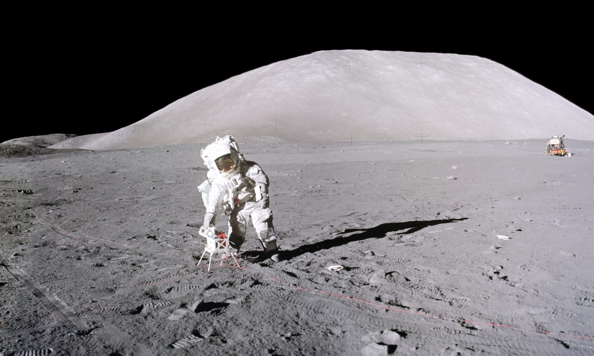
 There were 4 cable reels for the SEP antennae attached to the transmitter box. The attaching mechanisms were easy to open on Earth during training, but in situ on the Moon, they were much more difficult to unfasten. I promptly dropped 2 of the reels after I got them loose. Ron is slightly exaggerating the problem I had! The actual event is recounted in the ALSJ at 122:54:12. What is not exaggerated is the degree to which I am leaning to my right, one of the perks of working in lunar gravity (also see the website homepage for the wider view of this scene).
 (Copyright © 2014, by Scott Stantis, founder, Prickly City)
At the end of EVA-1 as I was trying to squeeze through the entrance hatch on my stomach with the PLSS scraping across the top of the entrance way, I made this comment in answer to Cernan (also in Chapter 10):
“Cernan looked up to see how I was doing with entering the hatch and said, “Jack, get down [lower] a little bit more, and you’ve got another 2 or 3 inches [before you are clear]”.
“ ‘I can’t get any lower, Willie. Me buttons are in the way.’ ” Here I quoted the caption of a famous Bill Mauldin World War II cartoon that had Willie and Joe face down in the mud with bullets flying close overhead.
 Bill Mauldin’s famous WWII cartoon caption I quoted while squeezing through the entrance hatch of the Challenger at the end of EVA-1. It originally appeared in the Stars and Stripes (Mediterranean Edition) for July 3, 1944 (Copyright © 1944 by Bill Mauldin. Courtesy of the Bill Mauldin Estate LLC).
Copyright © by Harrison H. Schmitt, 2023, All rights reserved.